9)
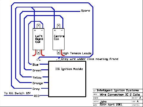
Fit the GREY wire under the frame of the coils Fit the BLACK
wire to the BATTERY Negative terminal, NOT FRAME DIRECT! Fit the RED wire
to the wire disconnected from the coils common wire this is now the supply +12Volt
for the module. See Wiring Harness and Connector data sheet. UNIT DAMAGE will
result if there is a short circuit from earth/frame/Supply to the following Module/coil
wires BLUE, GREEN, ( YELLOW is not normally used on 180's ) check your connections!!!!
If a fuse clears then there is a problem with the wiring do not replace fuse until
you have cleared the wiring fault. UNDER NO Circumstances should the Mauve/Purple
tacho wire be connected to the ignition coils directly or indirectly. It only
drives the electronic tacho, disconnect the tacho from any coil connection you
may have if you use the modules tacho mauve wire. Failure to observe the above
will almost certainly damage the module. NOTE!
The ignition module fires in a sequence of 1-2-3 ALWAYS! therefore any engine
firing sequence is done at the COIL END! This may seem confusing but it is quit
simple to use once the connections are established. See Harness Wiring Detail.
suppliers have this product or RS Components product
10) Fit
New Stator plate/Shaft Encoder to the Engine using the following order:
5 mm Screw-Spring Washer-SS Washer-Stator plate/Encoder. When using stainless
steel screws in aluminium, a small amount of copper grease should used to prevent
"balling" ( thread tearing in the aluminium ). Auto number 557 073.
11) Fit
New Rotor Assembly to the Crank Shaft, locating the indent on the crankshaft
to the set screw located on the new rotor.
12) Check
that the rotor passes through the opto switch slots without contacting
the sides of the slots. This is a fiddly job
and great care must be taken
to ensure reliable operation. If the rotor does contact the sides of any opto
switches the set screws locating
the rotor blade can loosened and the blade
located for correct clearance, retighten the set screws ( these are shipped with
Loctite adhesive on the screws ). If the spacing is not too far off then slight
bending of the actual aluminum Rotor is ok, however check all opto switch clearances
by rotating the crankshaft. The alternator coils now come very close to the magnetic
flywheel outer spider hub ( hence no washers on the supplied screws ) the most
important clearance is the rotor/shutter to bottom of the alternator coils this
should be around 2mm or more, to maintain this clearance the alternator coils
are " spaced " outward to the maximum available, as there may be engine to engine
differences, this operation may require checking and adjustment to get ALL of
the clearances correct. Install the flywheel with locking nut and rotate the flywheel
checking through the spider holes that there is clearance available between the
coils and the inner spider surface....not easy to check...we have found you can
hear it dragging on the coil plastic or even the pole faces of the coils dragging
on the magnet surface proper if they are not correctly spaced as well. The above
operation is only required on the 10mm thick replacement stator plate, we can
supply 6mm or 10mm depends on what is available in Australia at the time.
Once all the clearances are completed and checked, locking adhesive should be
used on the alternator coil mounting screws ie loctite 290. You must stop any
screws loosening in this area due to vibration as severe damage could result from
dislodged parts.
Reconnect the Battery Negative terminal to the engine/frame
Electrical Test and Diagnostics WARNING:
Since the end of 2004, a new module is available. The difference is that there
is no more Red and Green leds, instead there is a number display. This display
not only shows numbers but shows idle low, idle normal and engine above 1235rpm,
by a rising bar in the display. I find this display so easy to see and set the
correct idle as the bar moves up and down.
Test position E now says "1" for
cylinder 1 and 3 triggered with 1000rpm sparks on the Left and Right spark plugs
with the display saying "c" when TDC is found and of course "2" for the centre
cylinder.
Test position F now starts at "1" for 1000rpm and so on to "9"
for 9000rpm and "0" for 10,000rpm.
Test position F drives the coils hard
if you need to test ignition coils for a temperature problem, is ever required.
However test position E is a low power test position and can be used almost for
hours at a time if ever needed, hope i make sense.
The Decimal point on the
display is the power ok signal to the Crank Shaft Encoder module, ie if the decimal
point is ON the Encoder is powered ok. There is no Grey wire at the Ignition Coil
end now, disregard the reference in the docs to any Grey wire.
Fit spark plugs to the ignition coil HT leads, resting on the engine case so they
are visible. a small amount of anti seize copper compound ( grease ) makes plug
removal and fitting less prone to damaging the threads. Auto suppliers have this
product or RS Components product number 557 073. Connect the Ignition Module to
the harness and switch on the ignition. On the module there is a Yellow light
that should be on, and an Orange or Red light on the encoder board, if not, there
is a wiring problem. If ok then turn off the ignition and if not done previously,
fit spark plugs to the ignition coil HT leads and leave them touching the engine
frame. On the module rotate the pointer on the switch to position F see Photo
2 or Diagram 4. Switch on ignition there should be sparks on all the spark plugs,
if so you are doing great! if not all are firing then there is a simple wiring
mistake. Note; The Electronic Tacho and spark plugs will indicate a chronometric
spark rate starting at 1000rpm increasing in 1000rpm steps until 10,000rpm is
reached. This cycle takes about 30 seconds to complete. Any missing sparks ( misfiring
) at the higher spark rate indicates suspect plugs or coils...a very handy test
to help locate misfiring engines and also can be used to " burn clean " fouled
plugs to save removal of tank and plugs when a plug fuel/oil fouls. We use discarded
spark plugs with the earth " tab " broken away giving about a 5m/m spark gap,
this gives an approximate condition for a sparkplug/cylinder under compression,
all our modules support this spark gap at 10,000rpm if you see misfiring at any
point then check for at least 12V available to the module, if ok then the coil/HT
leads/plug caps/sparkplugs are suspect. Email us for tech help if required. It
will then cycle again until position F is DEselected, If your Tacho indicates
any error during this test, then the error is in the Tacho.
Switch off ignition
by using the Kill Switch if Ok then turn off ignition switch. Switch on Kill switch.
Rotate Module switch to position E and turn on ignition. With the crank shaft
at TDC cylinder 1( Right and Left ) the rotor should be half way through the TDC
opto Switch on the encoder board. ( See figure 1 ) This is checked by the RED
light on the module being either ON or OFF, if it is blinking then you are probably
too far to the left and cylinder 1,3 is firing their spark plugs. Rotate the whole
Stator Plate to the LEFT to correct the blinking or to get the RED light to come
on continuously, if the RED light is on all the time then rotate the Stator Plate
to the RIGHT until it goes off. The above procedure is setting the REFERENCE Top
Dead Center (TDC) for the whole ignition system, any error here will give the
wrong signals to the ignition module with poor results the most likely outcome,
take the time to get this right. We have found it to be very precise with just
the slightest of pressure on the crank shaft giving an ON Light going to OFF when
the pressure is released when at TDC. The firing sequence can now be checked by
rotating the back wheel ( or fitting the Flywheel/Magnet assembly ). The first
cylinder to fire after the TDC reference is the Centre cylinder its spark plug
should spark and the Red/Green lights Flash when the rotor moves into the opto
switch no other plugs should fire at this point, if the other plugs are firing
at the same time then there is a wiring fault ( short circuit between BLUE or
YELLOW or GREEN or you are not using suppressor spark plug caps/wiring...naughty
). Continue with the rotation until the correct sequence is confirmed. Switch
the ignition off and rotate the switch on the module to the 0 position or position
6 (depending on what version module you have ).
For
the Hall Effect version this applies;
Rotate Module switch to position E and turn on ignition. With the crank shaft
at TDC cylinder 1 the rotor magnet should be just to the left of the TDC Sensor
Switch on the encoder board. This is checked by using the Red led next to he TDC
switch or as well as the RED light on the Main Module being either ON or OFF,
if the Red and Green are blinking then you are probably too far to the left and
cylinder 1 is firing its spark plug. Rotate the whole Encoder Board to the LEFT
to correct the blinking or to get the RED light to come on continuously, if the
RED light is on all the time then rotate the encoder to the RIGHT untill it goes
off. The above procedure is setting the REFERENCE Top Dead Center (TDC) for the
whole ignition system, any error here will give the wrong signals to the ignition
module with poor results the most likely outcome, take the time to get this right.
Hall Effect at TDC We have found it to be very precise with just the slightest
of pressure on the crank shaft giving an ON Light going to OFF when the pressure
is released when at TDC. The firing sequence can now be checked by rotating the
crank shaft in the normal ( clockwise ) direction and confirm the correct sequence
ie Right +Left Then Centre.
The first cylinder to fire after the TDC reference
is the Centre cylinder its spark plug should spark and the Red/Green lights Flash
when the rotor moves into the opto switch no other plugs should fire at this point,
if the other plugs are firing at the same time then there is a wiring fault (
short circuit between BLUE or YELLOW or GREEN or you are not using suppressor
spark plug caps/wiring...naughty ).
Continue with the rotation until the
correct sequence is confirmed. Switch the ignition off and rotate the switch on
the module to the 0 position. That completes the calibration procedure.
With
the spark plugs fitted to the cylinders, fuel on, ignition on, starter engaged,
there will be flashes on the Modules RED light as the engine cranks indicating
that the trigger signals are being received from the encoder ( the yellow light
stays on all the time that the ignition is switched on ) and the engine should
fire.
The IDLE may have to be adjusted to about 1000RPM after warming up.
Setting the Idle Speed The Tacho as fitted to most Motorcycles is an indicator
not a Scientific Instrument ie; its accuracy can be poor.
On the module 1000rpm
is indicated by the Red Light being on and the Green light just coming on, 1000
to 1250 is indicated by Red and Green on with 1250RPM and above both lights go
off. 0-1000RPM 1000-1250RPM 1250-8375RPM 8375 and up Red Flashing Red and Green
on Red and Green off Red on= RevLimit
The different curves may be selected
while the engine is running. Positions 0 to B only. Please Note on the dual 120/180
module's position 6 to B are for the 180 selection 0 to 5 are for the 120.
If your Ignition module connector has ID120 or ID180 written on it, then the correct
firing sequence is automatically loaded. You may use 0 to 5 for both 120 and 180
and 360. e.g. the 180 equivalent of position
0 = 6 Low Advance, early rev
limiter
Curve 0 1 = 7 Medium Advance, 8375RPM RevLimit
Curve 1 2 = 8
General Purpose, easy advance
Curve 2 3 = 9 Performance engines only!
Curve 3 4 = A Simulates "Original" 180 Advance
Curve 4 5 = B High RPM Retard,
typically free flow exhausts
Curve 5 E = Encoder (Crank Shaft ) test for
120 and 180 F = Spark test on all cylinders 120 and 180 C and D are for future
use and if selected will give curve 0 all switch positions are valid. Suggestion
only: Select
position 0 to try out the rev limiter at 6500rpm so that you know when it comes
on. Then try position 2 for low octane fuels/lower compression engines. Then try
position 3, if pinking is present, then go back to 2. 13)
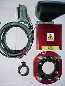
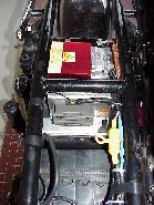
Find a suitable mounting point for the TA/TCI module away from engine heat, water
saturated areas, battery acid spills or fumes ( gasses ), etc. An area that has
cool air flowing is ideal. The Module is held in place by Velcro tape ( supplied
) and or a cradle with velcro. There are not a lot of good mounting points on
the 3C/Jota.
|
|
Possible place for the IIs module
|
14) Once you have decided on the appropriate switch settings, Fit the supplied
water proofing boot to the TA/TCI module as per Photo 5 or Photo 6 this boot must
also be sealed by waterproof tape at the bottom edge/ module area, a small amount
of RTV738 silicon sealer around the cable entry/boot point will also be required
to complete the seal. Note; PVC electrical tape is unacceptable for sealing use,
use Gaffa ( Nashua ) or Duct tape only. Also at the ignition coil end of the harness
a small amount of sealer ( RTV738 silicon sealer ) is used at the end of the black
sleaving/wire exit point to stop wind born rain entering and traveling back to
the module connection, this is important. The latest harness has thinner wire
for the coil connections etc. these wires must be fastened down with plastic Ty-Wraps
( or similar ) to prevent vibration failure, again PVC electrical tape is unacceptable
for this purpose, this is most important for the black battery wire from the new
harness, extra sleeving will be supplied to cover this black wire in the future.
How to set TDC Accurately!
TDC
is found by using a stopping device in the plug hole ( we use on old spark plug
body with the porcelain removed and a soft brass bolt in the body ) that stops
the piston just before TDC with a degree wheel attached to the crank shaft its
position is noted on the degree wheel ( a small reference mark on the case will
be the ref. for the relative degree wheel position ) then the crank is rotated
backwards until the piston stops again against the bolt in the spark plug hole.
Its postion is marked on the degree wheel, the bolt is removed from the plug hole
and the postion half way between the two points marked on the degree wheel is
TDC. From this you can now mark a point on the crank case 40 degrees to the right
from the TDC position. With the engine running the crank shaft will move between
these two points when a timing light is attached. Static start/idle is about 6
degreesBTDC rising to a maximum of 38 degrees on curve 3 or 32 degrees on curve
2. You only need to use an actual degree wheel to set the 40 BTDC position. If
you attach any type of disk and know the diameter then 40 degree can be translated
into length on the circumference by using the formule PI*d dividing that length
by 360 and multiplying the resultant by 40 = length of 40 degrees eg 150m/m diameter
times 3.14159 = 471.238 m/m circumference divided by 360 degrees = 1.3089 m/m
per degree therefore this times 40 = 52.35 m/m from TDC to the right is 40 degrees
BTDC. Encoder
details
UPDATE; as of March 2001 we have a new encoder, " Disco
model " it has diagnostic lights on all the cylinder triggers located on the crank
shaft encoder ( C/S ) board. TDC is checked by the Module or directly on the C/S
encoder board, all triggers will light their respective lights when the rotor/shutter
pases through the slot. Unfortunatley this encoder is not compatible with the
previous opto encoder We designed this new unit to facilitate a one ignition module
( I mode ) fits all policy. The I mode 120 ignition module will run ALL Laverda
engine types with either Opto or Hall effect encoders. The benefit is that we
will supply to various owners a spare 120 I mode module as local backup field
failures are rare, however if you are like us, being stranded is unacceptable...a
little preparation will help you on your way. This encoder has a number of field
derived improvements, There is now a small Orange or Red light on the green board
which glows when the Battery Voltage is Between 12 to 15 Volts ( ignition on )
however if the Battery Voltage falls below 12 Volts the light will become progressively
dimmer until at 9 Volts it will be off, the encoder will work down to 7 Volts
Cranking Start with the yellow light on the TA/TCI module indicating all is ok
when glowing. The purpose of this Orange/Red light is to indicate a failing battery
at start time ie; while cranking the engine on the starter motor,
Yellow
on and Red flashing at the TA/TCI with Orange encoder light on = all ok
Yellow
on and Red flashing at the TA/TCI with Orange encoder light off = low battery
volts/difficult starting
Yellow on and no Red Flashing at the TA/TCI with
Orange encoder Light off = do not waste your time, no starter motor starting possible,
Try clutch/bump start.
Yellow on and no Red Flashing on the TA/TCI = no starting
possible, diagnose the problem before you flatten your battery with useless cranking.
No lights on at all, no starting possible Whats
New and Upgrades;
We knew that field upgrades from on going development
would occur, to maintain all installations with the latest improvements all of
the system is plugable ie all encoders can be upgraded on the supplied harness
if you want a later product/upgrade then this can be done for a nominal charge,
for example, to convert from opto to I mode opto/halleffect the encoder is swapped
the rotor/shutter is swapped and inside the ignition module a printed circuit
board is swapped. This requires only limited skills, all removed parts can be
traded back to us. At this point in time we are happy with all advance Curves,
they are stable. UPDATE; as of March 2001 we have a new encoder, " Disco model
" it has diagnostic lights on all the cylinder triggers located on the crank shaft
encoder ( C/S ) board. TDC is checked by the Module or directly on the C/S encoder
board, all triggers will light their respective lights when the rotor/shutter
pases through the slot. Unfortunatley this encoder is not compatible with the
previous opto encoder. We designed this new unit to facilitate a one ignition
module ( I mode ) fits all policy. The I mode 120 ignition module will run ALL
Laverda engine types with either Opto or Hall effect encoders. The benefit is
that we will supply to various owners a spare 120 I mode module as local backup
field failures are rare, however if you are like us, being stranded is unacceptable...a
little preparation will help you on your way. Ignition
Coil Information and technical details
Replacement Ignition coils The replacement of ignition coils on older Laverda
engines is a straight forward selection process. ( the use of a digital multimeter
will help in selecting a suitable coil, they are inexpensive these days ) Primary
resistance, 2.5 ohms and above ( higher ) Secondary resistance, usually between
8K and 14K ohms ( 8000 ohms to 14000 ohms ) The newer " electronic " coil types
are better for digital ignitions due to the fact that the primary and secondary
windings are electrically ( galvanicly ) isolated, meaning you cannot measure
any resistance between primary and secondary connections older coils usually have
around 3 ohms to 14Kohms resistance between primary and secondary connections
Modern multi cylinder engines can have the very new, low primary resistance (
inductance coils ) basically these can only be used on our TCI system. Due to
their very low primary resistance ( .5 to .8 ohms or R5 to R8 ) they will damage
and render inoperative the TA module if used.
Typical after market replacement
coils are the Dyna DC1-1 twin output coils, these are very useful on the 180 configuration
allowing the use of 2 twin output coils. One coil feeds the outer two cylinder/spark
plugs, the second feeds the centre spark plug from one output the other output
is connected to the engine/frame via a High Tension ( HT ) lead, looks unusual
at first however it is a good way of being able to swap coils if a fault is suspected
in an ignition coil. Not generally known is the fact that twin output coils require
the spark plug gap to be reduced on their respective plugs ie .4 to .5mm instead
of the usual .6 to .7mm. This is due to the fact that the total air gap is the
sum of both plugs and can/will stress the ignition coil if too wide. We have available
on our TA a triple coil drive for the 180 engine ie 3 separate coils can be used,
the TCI can also use this mode however two coils must be wired in series. Some
ignition coils are so poorly manufactured that they reflect large voltages back
to the electronic ignition modules that they will damage the module permanently
or leave you stranded, one such type is Bosch GT40 a coil suitable for points
only systems. High
Tension Leads.
The use of silicon carbon ( graphite ) HT leads
on motorcycle engines is not permitted, the graphite fails from the vibration
and starts to arc internally leading to multiple open circuits and the ultimate
failure of the ignition coil due to high reflected voltages into the coil with
internal arcing rendering the ignition coil permanently damaged. PVC or Silicon
leads of 7mm diameter copper wire conductors are the usual type of HT lead used
on motorcycles. These leads then require suppressor caps at the coil or plug end,
typical Laverda equipment are the NGK 5Kohm type ( model type SD05F ) the use
of suppressor caps is not just for interference suppression the real benifit to
motorcyles is the elimination of cross firing ( cross firing can lead to substantial
engine damage if left to continue ) racing engines included!! unless special resistor
spark plugs are used. Inductively suppressed leads are my personal choice, these
consist of stainless steel wire spirally wound on a fiber glass core with silicon
outer insulation and are terminated with stainless steel connections with spring
steel clips covered by high grade silicon water proof boots .....simply the best
choice. These leads do not adapt well to older " spike " style coil HT termination,
although we have several 180's using these leads on Nippon Denso OEM coils on
Laverda's, email us for more detail. Spark
Plugs
We have had no success using Bosch spark plugs on Laverda
engines, poor starting, non existent idle, even on new plugs. Perhaps your experience
is different. We recommend NGK B8ES ( or B7ES for engines prone to oil fouling
). Operating
Instructions
Your new didgital ignition may require a different
starting technique than what was used before. 1) Cold engine, choke is required,
normal starting technique, if engine fails to start first press of the starter
button, wait at least 2 seconds before pressing the starter button again. This
is due to the fact that the IIS module is trying to " learn " what the crankshaft
is doing, if the engine does not start, then a reset period is invoked for 1.6
seconds after releasing the starter button, during this period no engine starting
is possible. A relaxed start operation will result in the engine starting within
2 crank revolutions or within 2 seconds, whichever is less. Constant stabbing
at the starter button is not the best way to start a Laverda. With the IIS module
first press start is all that is normaly required. 2) Warm/Hot engine 180's seem
to start best no choke, 1 to 2 twists on the throttle ( Dellorto pumpers ) press
the starter with a slight opening of the throttle at the same time will start
the engine. As most owners know thier engines well, a little experimentation will
give the best start technique for your engine. 120's seem to require choke at
all times to start reliably, again first time starting is normal for the IIS module.
Post
Installation Problems
After installation of the IIS module some
owners found that there appeared to be " new " problems. Basicly this is due to
a previous poor ignition hiding poor carburettor tuning, after fitting the IIS
module ALL carburettor problems are now VERY evident. We use various tools to
setup the engine after IIS installation ie mercury manometer, ignition control
panel that disables individual spark plugs and measures ignition coil performance.
Setting up the carburettors for us is best done with the manometer or individual
manometer operating on the air intake side if no balance spigot is available,
we set the cutaway to about 6.5mm on the centre carby and the other two also at
6.5mm ( some carbies required 7.5mm ) idle pilot ( air ) screw 1.75 turns out
from fully in ( if you cannot maintain idle use 2 turns out or more....runs very
rich so plugs will carbon foul in a short time ). Blipping the throttle gives
a temporary hign idle, settling after 1 to 5 seconds is an indication of lean
idle pilot. Black smoke at idle...too rich. Blipping the throttle from idle, engine
stumbles then revs clean.....too lean for the transistion phase of the carby...1/8
turn out on the idle pilot.. repeat last procedure until transistion is smooth....probably
runs rich at idle now....welcome to Dellorto's.
Some of the things to check;
Symptom
1) Hole at mid to upper rev range. Float level, needle and seat
check
2) Hole from idle to first gear take off Tricky one this, try 1/8 turn
out on the idle pilot screw....lots of likely causes, email us.
3) Hunting
at constant throttle Check for worn slides
4) Pinking Try going down one
switch position, 2 is a good curve to begin with.
Contact
for enquiries iismail@optusnet.com.au
|