How
to make adjustable camwheels on Laverda sohc twins (by courtesy
of Phil Todd) WARNING:
The following advices and informations are purely indicative and by no means the
responsability of the author of this article and/or the webmaster. Everyone has
to be
sure that he is able to repair or maintain himself his motorbike, if
in doubt, leave it to professional mechanics.
As
I've not seen any threads about the twin's cam setup details - I presume everyone's
happy with theirs, or, probably as it's such a pain in the backside job to sort
out no one wants to approach it - I suspect the latter!
I will describe
a way to make the cam timing adjustable overall and adjustable between each cylinder.
This is not really within the scope of all owners as access to workshop machinery
is required. Along the way I'll mention a few observations and tips which you
may find useful. Where realistic - I will also suggest areas that can be sorted
with hand tools.
The job can be done in two parts as you will see later.
I'll drop in a bit of history about why I decided to do this, so if you
only want the info - skip the next couple of paragraphs.
For a long time
I've enjoyed building performance Laverda motors - but know full well that to
leave the cam timing wrongly set can waste a lot of hard work & expense.
The
triple is no problem, but the twins are a lot more difficult.
My first effort
- after finding a 6 discrepancy between the cylinders was to use a 3/16" (4.5mm)
and 5mm piece of square steel, with one side milled to 4mm (the original key size)
and the opposite side milled to 4mm, except for the portion that goes into 1 cam
half - that was milled on the other side - even difficult to explain let alone
do!
After days of testing, with the cams and head removed several times, including
a blunder where I put the offset key in the wrong way round and ended up with
about twice the original problem! I got it almost right so bolted it all up. I
was never happy doing this,- it was a bas---d of a job - also keep removing/replacing
the cam flange wasn't doing it any favours either.
About this time a few of
us were proddy racing the twins in the Classic club - we started to run into serious
problems with the crankshafts shearing the centre joining splines - I looked at
loads of possible remedies, including using triple parts - I noticed that the
cam chain drive sprocket on both cranks was the same dimensions. A light switched
straight on in my head - The camshaft sprocket must then be the same dimension
on both models, the twins duplex chain has the same specification as a triple's
- just doubled up.
I don't doubt that many others already realised this, but
it was a gift for me.
I soon checked it out - and, Bingo, I knew straight
away the cam timing problem was as good as solved. PROCEDURE
1: As
I've not done this job for about 10 years - I hope my recall is accurate enough.
I know this may sound strange, but anyone who wants, and does start to do
this job, will most likely have the skills and knowledge to be more than capable
of finishing it.
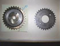
Firstly, obtain a couple of triple camwheels - most dealers will have an excess
of these - especially used - and be delighted to "offload" some of them - don't
get fleeced - phone round!
On the twin's camwheel visually check the original
timing mark's relationship with the keyway and position relating to the "hills
& valleys" of the teeth.
Measure the distance between the rows of teeth on
the duplex sprocket, then grind them off where they are hardened - you could even
use an angle grinder.
Then mount wheel in a lathe and remove the rest of the
lower, softer, area down to the original centre diameter at base of teeth.
Skim
the area between the mounting flange and outer evenly on both sides to give the
same width as measured between the two rows of teeth.
If you have to go a
bit narrower to get area perfectly flat and blemish free, a bit of leeway is Ok,
but the inner faces of the triple wheels can be relieved in that area if necessary.
|
Bore
out the triple camwheel's centres to be a snug fit over the twin's centre boss.
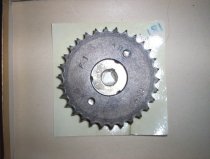
Mount both wheels over the centre bosses, then align the teeth - the duplex
chain can be looped round and secured to do this.
Using a 6mm drill, carefully
bore 3 holes spaced equally at 120? through the whole assembly. These holes are
at a larger PCD than original tappings - you will see why when doing the job.
Set up wheels to make sure you will miss the original tappings during this
procedure.
Separate wheels - Tap 3 holes to 7mm in one wheel and increase
the other wheel's and the "new" centrepiece's (CP) holes to 7mm.
Bolt whole
assembly together with new 7mm bolts, then make a timing mark in the same place
as original, using your previous record.
Mount the CP on a rotary table and,
with a 7mm slot drill or end mill, elongate the 3 holes to allow the teeth of
new camwheel to move just over ¼ of a tooth. This job can be done, or completed,
carefully with a file.
The whole assembly is, unfortunately heavier than original
- I have drilled lightening holes in mine, but still am a tad heavier. As cams
run at half engine speed it is not so bad. I lap the new wheels to the CP with
grinding compound - not sure if this is necessary - don't get any between centre
boss and wheel.
You now have the facility to adjust the overall cam timing. |  |
PROCEDURE
2: For
this procedure the right hand cam (RH) is the dynamo drive side, the left hand
(LH) is the primary drive side. This will enable timing to be adjusted between
cylinders. This job can be done on its own, no need to do procedure 1 first. Obtain
a length of 4mm keyway steel - a bearing shop or engineer's supplier will have
this. |
Using
a 4mm carbide or similar tipped end mill, elongate the woodruff key slot in each
cam half to full length of flange.
Elongate the 6mm mounting holes in the
LH cam flange to allow just over ¼ of a tooth of movement either way - this will
only be a couple of mm at this PCD.
The holes can be elongated on a rotary
table with a 6mm slot drill or end mill. Once again - they could be done, or finished,
with a file.
Cut and shape the 4mm keyway metal to finish up so that it does
not protrude past the mounting end of flange I.E it does not enter camwheel.
Fit
flange to cam half. For the RH cam - cut & shape the keyway metal so that it protrudes
into about halfway of the thickness of camwheel, but must not touch the LH cam
half when bolted up. Fit flange to cam half. You may be wondering why I suggested
elongating the RH half's slot, as it really is no different in operation than
it was. - It is because I consider the original to be a weak point anyway.
As
the flanges are removed/replaced, each time they lose a tiny bit of their grip.
If flanges are a loose fit on shaft, no extra pins, grub screws or whatever are
likely to stop disaster happening. I would be among the first to point out that
the key only locates an outer in normal circumstances, but there is, I believe,
a design "blemish" here. I believe that, as the flange has quite a thin wall,
the key, which is a good tight fit, actually embellishes (I've found another good
word) the metal to metal contact in this application and benefits from being present
along the whole length of flange.
I do lap the flanges to camwheel before
fitting to cams. Bolt the two halves and camwheel together and check that the
movement is available. |  |
ASSEMBLY
& CHECKING:
For this I am presuming both procedures have been done - for those only doing
procedure 2 - the last bit will apply.
Reassemble top end, with the cam flanges
tightened to camheel, but the new camwheels only tight enough to allow CP to move
independently - leave off top cover - make spacers to allow head to be pulled
down.
Mount dial gauge and timing disc and check RH cam - it can now be set
to where timing is correct as CP can be moved a little whilst camwheels remain
stationary then lock the bolt that is in view, then rotate crank to gain access
to the other 2 and tighten them also.
Check the LH cylinder's timing, and,
if required, adjust timing to be the same as RH by loosening off the flange nuts
and rotating RH assy independent of LH to get setting required.
Tighten nuts.
See my thread on triple camshaft timing - most of the checking procedure
is similar to the twins.
I've used this method on 3 of my motors - including
my 90 motor - all have been raced - all have the stronger SFC type valve springs
- none have given any problems. |
|

