WARNING: The following advices and informations are purely indicative and by no means the responsability of the author of this article and/or the webmaster. Everyone has to be sure that he is able to repair or maintain himself his motorbike, if in doubt, leave it to professional mechanics.
In
my experience, one of the worst problems of trying to set up or evaluate any Laverda
is the matter of setting up the cam timing.
It is the most neglected area
of any assembly work - especially as it doesn't add any tuning parts or cost a
fortune! I have seen on many forums article after article asking - "how fast?"
- "What MPG?" - "What jets?" - "What BHP?" - "What ignition timing?" etc. Unless
you are comparing like with like the answers will all be different.
The following
text is aimed at anyone with an interest in building a single motor to help make
it run as it should. There are many other factors as well, but I'll keep this
only on the cam timimg.
Firstly I should point out that, as long ago as
the early 1980's, I found very few of the Laverdas I checked had the cam timing
anywhere near good enough to leave as was. i will admit that many customers that
were interested in having this done had "twiddled" with a few bits themselves
- a prime candidate was the fitting of 4/C cams to A11 wheels. This usually gives
a power loss in the mid range and increases fuel consumption - often aided & abetted
by a 3into 1 exhaust system.
Having said that, the worst laverda I ever saw
was an RGS that made a puny 46bhp on our dyno - it had been correctly fitted with
a brand new factory supplied 4/C cam set (i.e. Cams with the corect wheels fitted)
- but the exhaust cam was a massive 23 degrees out of time! Just in case anyone
thinks that by fitting the correct wheels (or tapping theirs to factory spec)
to their cams that their troubles will be over - it may help...
The only
way to do it is to do it properly - set it up with a degree disc & clock gauge.
You have to realise that the tapping (7mm) in the wheel has to ultimately know
exactly the relationship between the "hills & Vallies" of the crankshaft teeth
in comparison with the centreline of the crankpin, via the relationship between
the mounting holes to the lobe centres, throw in one way wear on all teeth, possible
variations in distance between crank & cam C/L's plus other general machining
tolerances and you will understand it is difficult for any manufacturer, especially
older factories, to cope with this.
For a one off job, where you only
want to set up your own engine and then leave it alone, this is my simple suggested
way to initially set up the cam timing.
I always check the timing at maximum
lift on the lobe furthest from the camwheel. Max lift is the ONLY point that
will be known accurately on initial measuring, regardless of valve clearance.
* HOW TO CALCULATE MAX LIFT?
Simply calculate by adding opening and closing figures + 180 then divide by two, then minus the opening figure for IN and closing fig for EX. Example of A11 cams: (A11 Inlet)Open 46 close 82 = 128 + 180 = 308 /2 = 154 - 46 = 108. Max Lift for A11 IN is 108°. All the opening and closing figures are here |  |
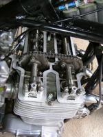
* HOW TO MEASURE FOR MAX LIFT ON A TRIPLE ENGINE?
This
procedure is for a Series 1 180 - but, apart from mounting the disc it's the same
for the later (inc 120 ) models.
Make a "positive stop" from an old spark
plug, by removing all the ceramic guts and the electrode. Weld an 8mm nut on top
of modded plug. Use an 8mm bolt with at least a 65mm threaded portion as the stop
- I've put an aluminium insert in mine to avoid any possible piston damage. You
could use an aluminium bolt or threaded studding. If you have completely sealed
the top of old plug with weld, drill a compression relief hole in its side.
Attach a 1/16" (1,5mm)diameter length of welding rod probably 3-4" (75-100mm),
with the free end sharpened to a point, to your dial gauge - I use a std electrical
terminal block to do this, then sharpen one end of a suitable length of 1/8" (3mm)
welding rod and make a hoop in the other end to fit over 6mm bolt, then bolt this
to one of the top starter gear cover fixings.
Remove alternator cover, set
motor to TDC and remove flywheel nut.
File or drill out the degree disc to
fit over the exposed thread, fit nut loosely, then bend the rod attached to the
inner cover to almost touch the disc, set up disc with a TDC mark aligning with
your new pointer.
Tighten up alt nut - ok if you have metal disc - if using
plastic use a washer either side of it.
On mine I have made an adapter to
replace alt flywheel, then use 2 x thinned nuts to lock disc assembly and turn
crank.
Remove cambox cover & spark plugs, rotate motor about 40 degrees away
from TDC and insert the Positive stop (PS) in the cylinder on TDC. Screw bolt
in fully in PS then carefully and slowly rotate crank (with degree disc attached)
back towards TDC, note reading where piston is stopped by PS, then rotate engine
the other way until piston is stopped again - note reading. True TDC will be when
both readings are the same.
If, for example, you have one reading of 20 degrees
and the other of 26 degrees, move the pointer or adjust disc to 23 degrees, then
rotate again to double check readings are the same.
For some this may be the end of the line, as, whilst you now know true TDC for one cylinder, do the same setup for the other two to check crank phasing is OK. If it's not, then you are wasting your time going any further. How much tolerance should there be? I can't say for sure - I would like to see less than 1 - if it's 4 or more stop the job now and decide on existing performance if you want to investigate further.
 | If
all is OK - remove PS. Make a steel support plate for the magnetic based dial
gauge holder. Mount plate to cam pillars of your choosing - I use a plate 10" (250mm) long by 2" (50mm) wide. A larger plate can get in the way a bit. Don't bottom out bolts holding this plate in pillars. Set primary drive side exhaust cam so that valve is closed - I use this side as it's the furthest away from drive and most likely to suffer the worst deflection - it will at least start off Ok. Mount gauge/holder assy on plate near to this valve - Set extended gauge probe to touch cam bucket in a position where lobe will not clout it when cam is rotating - use about 12mm of clock movement when locating probe, as bucket will move away from probe. Turn engine over slowly in normal direction of rotation - make sure cam chain is correctly tensioned- until dial slows and stops - note reading from disc, continue rotating until dial moves again - note reading. This is not always so easy to spot, do make sure that engine (if not in frame) is not moving about as crank is turned, also, especially after a rebuild with new pistons or rings, the rotation can be a bit jerky Also make sure that the probe is not "skating" across bucket surface -it is sharpened to a point to help avoid this. Do this procedure several times until you have the same reading each time. Use the average of these 2 readings to give you Maximum lift(ML) figure. E.G. - Dial stops at 70 degrees, starts again at 78 degrees will give 74 degrees as true ML. There can be a bit of confusion here as 74 degrees is also 106 degrees on the disc, which reads 90 degrees per portion, so 74 is 90 + 16 = 106 degrees. I believe the rest of Europe read it as 74 - it will be clear when you have disc in hand. I mark my discs with annotated (good word that) masking tape, so I can spot where ML is likely to be - could save a blunder or two. |
* WHAT TO DO IF ADJUSTMENT IS REQUIRED?
Let's
say your cam is 6 retarded and you want to run it on time.
6 is ¼ of a tooth,
so try flipping camwheel over to other side and remarking to see if that helps
as tappings are not usually exactly at bottom or top of "Hill or Valley" of tooth.
Some camwheels have 4 tappings, so try them all. That may well not suffice.
So
the next step is to file out the mounting hole in flange into a slot. Some people
are aghast at doing that, but the strenght of the bond between flange & wheel
is the contact area of metal to metal, not the bolts.If you could, for example,
tighten up a pair of 4mm bolts to the same amount, the wheels would not slip.
I have polished and drilled my wheels and am yet to have one slip.
The best
file to use is a 1/4" chainsaw file - it has very fine teeth and a parrallel shank..
set up the wheel and mark so that the minimum amount of filing needs to be done,
as room on the 180 degree flange is limited.
Test again and tighten bolts when
ML is where you want it.
Carry out same procedure on the inlet cam.
This
job can be quite frustrating, take a long time, or be very confusing. If you are
an impatient, bad tempered or ham fisted type of person - please don't attempt
it!
If you enjoy doing it and are pleased with the results, slot your wheels,
use nuts & bolts, modify head and pillars, then you can avoid so much hard work.
* HOW TO ADJUST TO YOUR OWN REQUIREMENT?
As
a general rule, moving lobe centers gives the following result:
Advancing
the intake and retarding the exhaust moves the power up in the RPM range and dramatically
affect the bottom end power.
Retarding the intake and advancing the exhaust
gives a wider power band but affects the top end power.
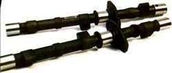
With twin cam engines
we can move the cams independently.
Example for triples equipped with 4C cams: For good mid range and no loss of top end power, a 4/C cam can be set with 4-7 advance on exhaust and 2-4 retard on Inlet. This can cure mid range problems - especially with a 3 into 1 exhaust - also gives more valve to valve clearance.
Caution: Moving lobe centers can drastically alter valve to piston clearance. The most critical is the intake and usually occurs somewhere after TDC. Make all adjustments in small increments and NEVER force the engine past any resistance until you know the cause.